3 and 4 way switch wiring diagram pdf
3-way and 4-way switches enable lighting control from multiple locations, enhancing flexibility in electrical systems. Wiring diagrams provide clear visual guides for installing these switches correctly, ensuring safety and functionality.
Differences Between 3-Way and 4-Way Switches
A 3-way switch has three terminals and is used to control lighting from two locations, while a 4-way switch has four terminals and is used in combination with 3-way switches for three or more control points. The 3-way switch is typically installed at the ends of a circuit, while the 4-way switch is placed in between, allowing for more flexible and complex lighting configurations. Both are essential for multi-location lighting control systems.
Importance of Wiring Diagrams for Installation
Wiring diagrams are essential for installing 3-way and 4-way switches, providing a clear visual guide for connecting wires. They help identify wire colors, terminals, and connections, ensuring safety and proper functionality. Diagrams prevent mistakes, such as short circuits or incorrect wire termination, and simplify troubleshooting. By following these schematics, even complex configurations become manageable, making wiring diagrams indispensable for both novice and experienced electricians working with multi-switch lighting systems.

Understanding 3-Way Switch Wiring Diagrams
A 3-way switch wiring diagram illustrates how to connect wires for controlling a single light from two locations. It shows the common, traveler, and ground wires, ensuring safe and correct connections for proper functionality.
Basic Components of a 3-Way Switch
A 3-way switch features four terminals: a common terminal and two traveler terminals, plus a grounding terminal. The common terminal is always hot, while the travelers act as pathways for the electrical current. These components work together to create a circuit that allows lighting control from two locations. Proper wiring of these terminals ensures safe and reliable operation of the switch in various configurations.
Common Wiring Configurations for 3-Way Switches
3-way switches are often wired with a 14-3 cable connecting the switches and a 14-2 cable for power and light connections. Configurations include power at the switch or light, with travelers connecting the two switches. Neutral wires are spliced at junctions, ensuring proper circuit flow. These setups allow for controlling a single light from two locations, with clear diagrams guiding installations for safety and efficiency. Proper wiring ensures reliable operation and meets electrical standards.

Understanding 4-Way Switch Wiring Diagrams
4-way switches control lights from three or more locations, using 14-3 cables for connections. They require a 3-way switch at each end and 4-way switches in between, ensuring proper traveler wire connections for reliable operation.
Basic Components of a 4-Way Switch
A 4-way switch features four terminals: two brass (hot) and two silver (traveler wires). It includes a grounding screw for safety. The switch connects between two 3-way switches, enabling control of a light from multiple locations. The traveler wires carry the electrical signal between switches, while the hot wire connects to the power source. This setup allows for flexible lighting control in larger spaces like hallways or staircases.
Common Wiring Configurations for 4-Way Switches
4-way switches are typically installed between two 3-way switches, using 3-wire cables to connect traveler wires. Power feeds can originate from a switch or the light fixture. Neutral and ground wires must be properly connected. The hot wire from the power source connects to the 3-way switch. Traveler wires link the switches, enabling multiple control points. This configuration ensures reliable operation and safe electrical connections in multi-location lighting setups.

Combined 3-Way and 4-Way Switch Wiring Diagrams
Combined systems use 3-way and 4-way switches to control lights from multiple points. Power can feed at the switch or fixture, with traveler wires connecting switches for reliable operation.
Power Feed at the Light Fixture
When the power feed originates at the light fixture, the neutral wire is connected directly to the fixture, while the hot wire is spliced to the traveler wires. A 14-2 cable typically runs from the fixture to the first 3-way switch, and a 14-3 cable connects the switches in sequence. This configuration ensures proper circuit functionality, allowing control of the light from multiple switch locations. Neutral wire connections are critical for safe and reliable operation.
Power Feed at the Switch
A power feed at the switch involves connecting the hot wire from the electrical source directly to the switch. A 14-2 cable typically runs from the power source to the first 3-way switch, while a 14-3 cable connects the switches in sequence. This setup allows multiple control points for the light fixture, ensuring proper circuit functionality. Neutral wires are spliced through the system, maintaining continuity for safe and reliable operation.
Downloading and Using 3-Way and 4-Way Switch Wiring Diagrams in PDF
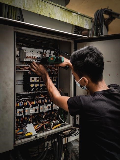
Download free PDF wiring diagrams for 3-way and 4-way switches online. These guides provide step-by-step instructions and clear visuals for safe and proper installation and configuration.
Steps to Download Wiring Diagrams
To download 3-way and 4-way switch wiring diagrams in PDF, visit trusted electrical resource websites. Search for specific diagrams, select the desired configuration, and click the download button. Ensure the PDF includes detailed instructions and clear visuals. Verify the source for accuracy and safety standards before use. Always follow the instructions carefully to avoid electrical hazards and ensure proper installation.
Tools for Viewing and Printing PDF Diagrams
Use Adobe Acrobat Reader or web browsers like Chrome or Firefox to view PDF wiring diagrams. For printing, ensure the PDF is scaled to fit the page. Use printer settings to adjust orientation and paper size. Zoom in for detailed views and print in high quality for clarity. Free tools like Smallpdf or online converters can also help manage and print PDF diagrams effectively.
Installation Guide for 3-Way and 4-Way Switches
Installing 3-way and 4-way switches involves connecting wires to terminals, ensuring proper grounding, and testing functionality. Use wire strippers, screwdrivers, and voltage testers for safe installation.
Materials and Tools Required
For installing 3-way and 4-way switches, you’ll need 14-2 or 14-3 cables, wire nuts, and the switches themselves. Tools include screwdrivers, wire strippers, and a voltage tester. A ladder and work light may also be necessary for accessibility. Ensure all materials meet local electrical codes for safety and reliability. Proper tools help ensure secure connections and accurate wiring configurations, reducing the risk of electrical hazards.
Step-by-Step Installation Process
Begin by turning off power at the circuit breaker. Use a voltage tester to confirm the wires are dead. Connect the black (hot) wire to the brass terminal on the 3-way switch, then connect the red traveler wires between switches. For 4-way switches, link the traveler wires to maintain the circuit path. Finally, attach the ground wire to the grounding terminal. Follow the wiring diagram to ensure all connections are correct and secure. Double-check all wire connections before restoring power.
Troubleshooting Common Issues
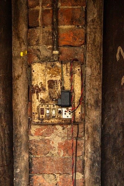
Identify common issues such as incorrect wire connections, power feed misconfigurations, and faulty travelers. Verify proper grounding and neutral connections to resolve connectivity and power problems.
Identifying Wiring Mistakes
Common wiring mistakes include incorrect connections between switches, improper power feed placement, and miswired travelers. Check for loose or reversed wires, ensuring the common terminal is correctly identified. Verify that all connections match the wiring diagram, especially in complex 3-way and 4-way configurations. Use a multimeter to test continuity and ensure proper grounding. Addressing these issues early prevents circuit failures and ensures reliable operation of your lighting system.
Resolving Power and Connectivity Problems
Power issues often arise from incorrect wire connections or faulty switches. Verify the power source is correctly routed through the switches. Check for loose or damaged wires, ensuring all terminals are secure. Use a wiring diagram to confirm connections, especially between 3-way and 4-way switches. Test for voltage at each switch to identify breaks in the circuit. Properly grounding and ensuring neutral connections can resolve many connectivity issues, restoring system functionality effectively.

Advanced Configurations and Tips
Advanced setups involve wiring multiple lights with 3-way and 4-way switches, enabling control from several locations. Smart switches can be integrated for remote operation, enhancing convenience and efficiency.
Wiring Multiple Lights with 3-Way and 4-Way Switches
Configuring multiple lights with 3-way and 4-way switches allows for versatile control from various locations. Start by determining the power source’s entry point—either at the switch or the light fixture. Use 14-3 cables between switches to accommodate traveler wires. Connect the common wire to the power source, and link traveler wires between switches to ensure synchronized operation. For multiple lights, wire them in parallel, ensuring each has dedicated power and neutral connections. Ground all metal components for safety, avoiding aluminum wire. Securely wrap wires around terminal screws and test the circuit with a voltage tester to verify functionality. Troubleshoot any issues by checking connections and wire integrity.
Integrating Smart Switches into the System
Integrating smart switches enhances traditional 3-way and 4-way systems with voice control, remote access, and energy monitoring. Begin by replacing existing switches with smart models, ensuring compatibility with the current wiring configuration. Use a neutral wire for power supply if required. Connect traveler wires to maintain communication between switches. Install a smart hub or bridge for seamless integration with smart home systems. Ensure proper grounding and follow manufacturer guidelines for installation. Test functionality through the app to confirm control from multiple locations, and troubleshoot connectivity issues by checking wire connections and network stability. This modernization allows for advanced automation and energy efficiency.
Safety Precautions and Best Practices
Always turn off power at the circuit breaker before starting work. Use a voltage tester to ensure wires are de-energized. Properly ground all circuits and ensure neutral wires are securely connected to avoid shocks. Keep work areas clean and well-lit, and avoid overloading circuits. Follow wiring diagrams precisely and use the correct gauge of wire for the application to prevent hazards. Regularly inspect wires and connections for damage or wear. Consult a licensed electrician if unsure about any step to ensure compliance with local electrical codes and safety standards.
Grounding and Neutral Wire Connections
Proper grounding and neutral wire connections are critical for safety and functionality in 3-way and 4-way switch installations. Grounding wires (bare or green) must be connected to all metal components, including boxes and switches, to prevent electrical shocks. Neutral wires (white) should be securely connected to ensure proper circuit operation. Always follow local electrical codes and wiring diagrams to maintain safety and avoid hazards like electrical fires or shocks. Proper connections ensure reliable performance and protect against potential risks.
Avoiding Common Safety Hazards
Avoiding safety hazards in 3-way and 4-way switch wiring requires careful planning and adherence to best practices. Always turn off power at the circuit breaker before starting work to prevent electrical shocks. Use properly rated wires and ensure all connections are secure. Never overload circuits, and avoid using aluminum wire for grounding. Follow wiring diagrams precisely and consult local electrical codes to minimize risks. Proper safety measures ensure a safe and reliable electrical system.
Understanding 3-way and 4-way switch wiring diagrams is essential for safe and efficient electrical installations. They provide clear visual guidance for controlling lighting from multiple locations. With downloadable PDF diagrams, professionals and DIYers can plan and execute installations with confidence. Adhering to these diagrams ensures systems are both safe and functional, meeting modern electrical demands.







Leave a Comment